This is the AMT / Ertl X/YB-35, a very large kit when built, but a unique subject. This kit takes some work, think of it as a limited run effort and you will be well prepared. I opened up the wing leading edge inlets and the wing slots at the tips. I also detailed the interior and wheel wells. The starboard drag rudder was scratchbuilt so it could be displayed in the opened position. All the gun stations were armed with Quickboost barrels. The finish is Alclad, six different shades in total. A build thread is posted to this blog for anyone wanting to see details of the construction process.
I forgot to mention something last week, so let me fix that first just in case somebody reading this builds one of these someday – I added more weight to the nose before I sealed up the fuselage. No danger of this one being a tail sitter because of the design having no tail, but after taping the major components together and balancing it on my fingers, I wasn’t completely convinced the nosewheel would stay down either. I ended up adding a little less than 1.5 ounces more, bringing the total to just under three ounces. Okay, the sanding is done (whew!) and the panels have been rescribed. All the sub-assemblies are fully prepped. Notice that the engine shaft fairings are labeled on the card, they are all slightly different and I am trying not to mix them up.Here is a closer shot of the nose area. The fit of the bubble-type canopies looks good, but those built into the main body are just a mess. You basically pick a side to mate up, and then try to feather in the rest. You can get an idea how bad this is by looking at the amount of putty around the clear parts. The underside is worse – there is a pretty good sized gap to fill there.Here’s the “Batterang”. Really, who primes with black? Anyway, the first coat of primer is on, a whole ounce! There are some filling touch-ups, thankfully minor. Here is a shot of one of the main gear legs. The center section is substantial, but if you look closely it is independent from the cross bracing above it. What actually supports the weight is the much smaller bracing extending to the corners. When I test-fitted this part there was a lot of play fore-and-aft. Given the soft plastic I was certain I would manage to knock this off and it was sure to be a messy repair. I drilled through the cross brace into the main leg, and superglued in a thick piece of copper rod. Much more solid!I wanted to arm the turrets, as I find this more visually interesting. For this I used the Quickboost gun set QB72055, designed for the B-25J Mitchell. Quickboost packages their detail sets for specific kits, but look a bit and get what you really need – in this case I needed .50 cal gun barrels. You get 15 .50cal barrels with the B-25J set, far fewer of the same barrels with their other choices. Likewise, if you want a very nice R-1830 Cyclone buy one of their “B-17 Engines” sets. Four engines for the price of one! I wanted to keep the spinners shiny, but the prop blades dull. With six different shades of Alclad, I’d had enough of masking tape to last for awhile. Here’s a quick trick – a mask made from a slotted piece of card. Slide it over the base of the prop and spray, move it to the next.
The finished article, all shiny and with all the fiddly bits flying in formation. The panels are six slightly different shades of Alclad. Masking was a bear but the finish is much more interesting than a monochrome finish.
These are the propeller shaft fairings, all four are slightly different. The cooling air scoop for the reduction gear fits poorly. Shape, fill, sand. The discharge air exits at the end of the fairing under the shaft. These outlets are not represented, but are easy to fabricate. I am hoping to shim the bases out a bit for a tight fit and add the fairings at the end of construction.Here is the finished cockpit, showing the added weight and the nose wheel bay. I have added about 1.5 ounces, hopefully that will suffice. There’s still a few options if it’s not enough, but overloading the gear struts is always a concern. The three crew seats have tape seatbelts, but they will be difficult to see when the model is closed up. The other four seats will be directly under transparencies, they will be equipped with photoetch belts and added later.Another shot of the cockpit, with a U.S. quarter for scale. I am modeling a “production” machine so I have used Interior Green, but the prototypes were natural metal inside. The green was drybrushed with lighter shades, and everything was given a thin wash of black when detailing was finished. The seat cushions could be yellow or O.D., the kit instructions call out red. Was red a SAC thing?Next is the major assembly, and to put back all the bits I’ve cut off. I am pleased with this build so far. There is a gremlin waiting, though. The main transparency was loose from the sprue and has a bad scar where it was attached. I’ll try to sand it out and hit it with Future, but it’s ugly.Well, she’s together, major assembly is complete. Got to say, the fit was terrible! This kit is reminding me more and more of a limited run kit – soft plastic, poor fit, ejector pin marks. Most of the bench time this week was spent filling and sanding, or cleaning up the sub assemblies. Just about through it here. The chaos on the workbench is spreading – 90% of the work gets done on a 3” x 6” spot on the edge.This is the underside of the wingtip slot. There are five structural supports inside, in some of the pictures of the actual aircraft these can be seen quite clearly. The forward part of the slot was constructed using the portion removed from the wing and two pieces of 0.1” quarter round. The inside was filled with casting resin to level it out.How do you control yaw without a rudder? Northrop’s solution was a “drag rudder”. Basically, the back of each aileron was constructed as a split flap. These could be employed together as speed brakes, or used asymmetrically to function as a rudder. Here is my attempt at modeling it, the background is a picture of the real deal under construction. Still have a few tweaks, but this is close. My intention is to only display one side open, to illustrate the “rudder” function.
AMT / Ertl’s Northrop X/YB-35. Italeri has re-popped this kit, but I had one of the older ones lurking in my stash. The empty gun turrets always bugged me, arming them will be the most visible change. Given how big the kit is, there are relatively few pieces. Don’t be fooled by the huge box, everything could easily fit into a Hasegawa box for a twin prop bomber kit if one sprue were laid out differently. Looking at pictures of the prototypes, you notice lots of open bits which are molded closed off. One of the first things I wanted to improve was to open the inlets on the leading edge of the wings. Simply hollowing out the kit part doubles the depth. I will extend these back some more, but this will require opening up the center wing section as well.And here is where all that cooling air comes out – three vents on the top center of each wing. There is a positionable door yet to fabricate over each, representing the “cowl flaps”.Another item to open are the wing-tip slots. The section cut out of the top portion of each wing will be built up and remounted, the bottom sections were flipped and faired back in to form the inner channel.Here’s a shot inside the outer wing panel. The AMT plastic is quite soft, the big assemblies are very squishy. No way they would stand up to sanding and handling if left alone. I beefed up the outer wing panels with Plastistruct and epoxied in an “I-beam” made from scrap oak. That should do it!Here’s the nose wheel well, the kit part is in the foreground. I have deepened the well and added ribbing. The strut attachment point is extended to the proper length using brass tube epoxied to the underside of the cockpit floor. The well actually extends to the bottom corner of the picture, the two doors covering the section where the wheel itself is stowed were closed except when the gear cycled. I have not found any good pictures of these wheel wells, but if typical they would be full of plumbing and equipment. Debating on how much to do in the wells, at least some basic plumbing where it is most visible.This is the cockpit, it looks like it would be right at home in a sci-fi kit. I have added fiddlybits based upon what could be seen in pictures, and guessed at the rest. No open canopies here, the crew entered through a belly hatch. The idea will be to create a busy feel for what can be seen through the transparencies. I have not added to the after stations, they will not be very visible.This shows the oak strip bracing added in order to strengthen the lower center wing section. AMT provides very little in the way of internal bracing – there are only two inserts for where the outer wing panels join, and those only come in contact with one surface. Here I have constructed a box beam out of scrap oak strip, and epoxied an additional strip further back. The wheel wells are used to anchor these, and it feels like this will work.The wing inlets were extended with 0.08” x 0.25” (2 x 6 mm) Evergreen strip, and the dividers extended with card. I am attempting to force some perspective here to give a deeper feel. To prevent the open look I’ll shoot some flat black into the center sections before I close them up. The upper inlet has internal bracing added, this is visible in some pictures of the prototypes. There are better pictures of the bracing on the YB-49’s, but the pattern may be different.
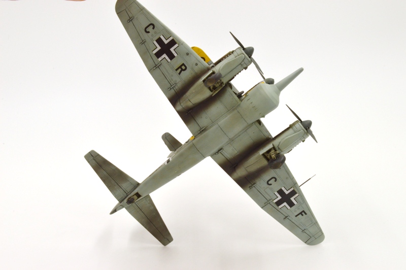
The Mistel (German for mistletoe) was a series of composite aircraft developed by Germany during the Second World War. They were composed of an unmanned Junkers Ju 88 bomber aircraft fitted with a two-ton shaped charge explosive warhead which was to be guided to the target area by an attached fighter, usually a Messerschmitt Bf-109 or Focke-Wulf Fw 190. When within a few miles of the target, the pilot would separate the fighter, leaving the bomber component to fly on autopilot to impact the objective. The lower components were intended to be drawn from “timed out” or “war weary” bombers which were utilized past their useful combat lives, but as Germany focused on increasing fighter production and operations more newer bomber airframes became available. The Mistel can be thought of as one of the first attempts at developing a cruise missile.
This is one of my first efforts at modeling a Mistel, with an aircraft combination photographed at Burg in 1944 as my subject. The upper component is the excellent Fine Molds Messerschmitt Bf 109F, the lower component an AMT Ju 88. Subsequently Revell of Germany and Hasegawa released superior Ju 88 kits which are both more accurate and better detailed, the Revell kit being the better of the two in my estimation, and cheaper as well.
WHENEVER ANY FORM OF GOVERNMENT BECOMES DESTRUCTIVE OF THESE ENDS (LIFE,LIBERTY,AND THE PURSUIT OF HAPPINESS) IT IS THE RIGHT OF THE PEOPLE TO ALTER OR ABOLISH IT, AND TO INSTITUTE A NEW GOVERNMENT― Thomas Jefferson
![B35Build31[1]](https://inchhighguy.wordpress.com/wp-content/uploads/2019/06/b35build311-1.jpg)
![B35Build33[1]](https://inchhighguy.wordpress.com/wp-content/uploads/2019/06/b35build331.jpg)


![B35Build39[1]](https://inchhighguy.wordpress.com/wp-content/uploads/2019/06/b35build391.jpg)
![B35Build37[1]](https://inchhighguy.wordpress.com/wp-content/uploads/2019/06/b35build371.jpg)
![B35Build35[1]](https://inchhighguy.wordpress.com/wp-content/uploads/2019/06/b35build351.jpg)


![B35Build16[1]](https://inchhighguy.wordpress.com/wp-content/uploads/2019/05/b35build161.jpg)
![B35Build17[1]](https://inchhighguy.wordpress.com/wp-content/uploads/2019/05/b35build171.jpg)
![B35Build20[1]](https://inchhighguy.wordpress.com/wp-content/uploads/2019/05/b35build201.jpg)
![B35Build21[1]](https://inchhighguy.wordpress.com/wp-content/uploads/2019/05/b35build211.jpg)
![B35Build22[1]](https://inchhighguy.wordpress.com/wp-content/uploads/2019/05/b35build221.jpg)
![B35Build23[1]](https://inchhighguy.wordpress.com/wp-content/uploads/2019/05/b35build231.jpg)

![B35Build9[1]](https://inchhighguy.wordpress.com/wp-content/uploads/2019/05/b35build91.jpg)
![B35Build10[1]](https://inchhighguy.wordpress.com/wp-content/uploads/2019/05/b35build101.jpg)
![B35Build11[1]](https://inchhighguy.wordpress.com/wp-content/uploads/2019/05/b35build111.jpg)
![B35Build12[1]](https://inchhighguy.wordpress.com/wp-content/uploads/2019/05/b35build121.jpg)
![B35Build13[1]](https://inchhighguy.wordpress.com/wp-content/uploads/2019/05/b35build131.jpg)
![B35Build14[1]](https://inchhighguy.wordpress.com/wp-content/uploads/2019/05/b35build141.jpg)
![B35Build15[1]](https://inchhighguy.wordpress.com/wp-content/uploads/2019/05/b35build151.jpg)
![B35Build1[1]](https://inchhighguy.wordpress.com/wp-content/uploads/2019/05/b35build11.jpg)
![B35Build2[1]](https://inchhighguy.wordpress.com/wp-content/uploads/2019/05/b35build21.jpg)
![B35Build3[1]](https://inchhighguy.wordpress.com/wp-content/uploads/2019/05/b35build31.jpg)
![B35Build4[1]](https://inchhighguy.wordpress.com/wp-content/uploads/2019/05/b35build41.jpg)
![B35Build5[1]](https://inchhighguy.wordpress.com/wp-content/uploads/2019/05/b35build51.jpg)
![B35Build6[1]](https://inchhighguy.wordpress.com/wp-content/uploads/2019/05/b35build61.jpg)
![B35Build7[1]](https://inchhighguy.wordpress.com/wp-content/uploads/2019/05/b35build71.jpg)
![B35Build8[1]](https://inchhighguy.wordpress.com/wp-content/uploads/2019/05/b35build81.jpg)